I’ve been asked to do a speech at work recently, and I have decided to do it on one of my favourite papers: “Building components for an outpost on the Lunar soil by means of a novel 3D printing technology”. This paper, as the name suggests, describes the potential implications of 3D printing on the creation of bespoke lunar bases. The paper was funded by the European Space Agency.
The paper highlights a main reason as to why the development of a lunar outpost would be advantageous to humans: due to the lower gravity on the moon, far less fuel would be required to launch space craft from this location. It then follows that for launch to be possible, an outpost sufficient for both human habitation and for the storage of scientific instrumentation would be required. There are numerous issues to be faced in this environment. There are the most obvious ones such as high temperature fluctuations and the risk of micrometeoroids, as well as the risks associated with cosmic radiation, and being based in a vacuum. The key to overcoming these issues would be too have a high level of environmental protection, i.e. very thick walls. The paper highlights three potential solutions to this requirement:
• Digging caves far under the lunar surface
• Transporting fully formed lunar modules to the moon
• Building structures directly on to the lunar surface
As the title of the paper suggests, the third option was found to be the most viable. The second option (transporting fully formed modules) can easily be ruled out due to the huge transportation costs of moving such large objects in to space. The first option would certainly potentially be more viable, as it only requires the transportation of digging equipment/operators to the moon. However, little is known about the subterranean lunar environment, and so various exploratory missions would be required. There is also a greater risk associated with so-called moonquakes when a structure is underground. Plus, it has less of a “cool” factor. As such, the rest of the paper deals only with the final option. This solution would also have the issue of energy requirements to transfer building materials to the moon, and so 3D printing using lunar regolith as a base material is proposed as a solution. This would require only a binding agent (and construction machinery) to be transported.
Designing the physical structure of the outpost is quite an interesting problem in itself. For simplicities sake, the decision has been made to decouple the task of maintaining an internal atmosphere from the task of providing protection from temperature fluctuations, micrometeoroids, and radiation. Based on this decision, it was decided that the atmosphere (and basic structure) could be provided by a pressurised internal bubble. The protection would be provided by a 3D printed lunar regolith shell. The protective properties would be ensured largely via a high thickness in this external layer. It would be impossible to create a 100% effective shield, and so the risk appetite for this project has been factored in. It was decided to aspire for radiation protection to be at a level where humans could spend 6 months-1 year in situ at a time without suffering ill effects, and that there should be a 99% probability of no micrometeoroid penetration over a mission lifetime of 10 years. It has been estimated that a wall thickeness of 1-2m should provide sufficient levels of protection, which should incidentally in combination with the internal bubble provide sufficient thermal insulation.
The location of this theoretical base is also a factor considered within the paper. As water has been detected under the surface of the moon near the southern pole, this would be the most likely candidate area. It is also proposed that the outpost be located on a higher area, such as the edge of a crater. This is to ensure that it has optimal access to sunlight for solar panels. It does seem likely that this lack of shelter would increase the chance of micrometeoroid impact however, making the shielding all the more important.
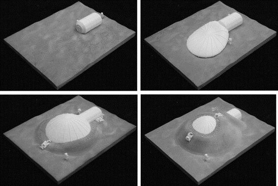
As previously stated, an internal pressurised bubble would provide not only an atmosphere for the human environment, but also a basis for the shape of the outpost. It is proposed at a later point in the paper that an inflatable inner shape could be used to provide a support for the 3D printed material during extrusion, which could later be deflated and reused for future modules. Due to the shape of the internal bubble, the overarching shape of the external shell would be a curve. This can be seen in figure 1 of the paper, which demonstrates how the shell may be built up over the internal bubble:
In the creation of such a shape, the structure load is an important factor to be considered. As such, three main contributing factors have been identified:
• Gravity
• Moonquakes
• Thermo-elastic load
The principles of handling both gravity and moonquakes are quite similar to the problems faced on earth, although to a slightly lesser degree. The factor that is most different to the experience on earth is designing to compensate for the thermo-elastic load. With the proposed location of the edge of a crater at the south pole of the moon, the sun would slowly rotate around the base over a space of 29 days. This means that there will be a temperature gradient between the areas in direct sunlight, and those that are not. Because of this, the relationship between the coefficient of thermal expansion and the mechanical strength of the bound regolith shell would need to be carefully considered in the infill structure design.
It has previously been stated that the shape of the structure should be a continuous curve. A internal height of 5m is proposed, as this would allow for two internal levels. A diameter of 10m has also been proposed. The proposed internal design of the module can be seen in figure 2 of the paper:
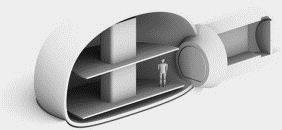
To have an internal usable space diameter of 10m and a height of 5m, quite a large physical footprint would be required. To reduce this, it has been proposed that the module could be somewhat placed underground. In the above picture, it can be seen that while the top of the module is an arch, the sides are almost horizontal. It is proposed that the structure could be buried so that the horizontal sections are below the lunar surface, with only the bubble top remaining outside. It is unclear on how this would work with the access tunnel being as illustrated above, but it seems possible that the entrance could simply be on the upper layer of the structure.
With the proposed internal dimensions decided, it was next necessary to propose the external dimensions of the 3D printed shell. In the decision making process, three main requirements needed to be fulfilled:
• The arc of the structure needs to be within the angle of repose of the regolith, meaning that the angle at which the structure will not slope under the effects of the lunar gravity. This was estimated to be around 40 degrees.
• Sufficient protection from micrometeoroids, implying a fairly even spread of thickness.
• Sufficient protection from solar radiation, with increased levels of thickness in the directions facing the sun, as a large amount of the radiation experienced within the environment is associated with solar flux.
As a basic shape for the internal profile of the shell, a catenary arch was chosen. A catenary is the name of an idealised curve formed of a chain or rope hanging between two points under its own weight. Catenary archs are used a lot in architecture, as they consist of the optimal load balancing of material. An example of a catenary arch can be seen in the image here, taken from Wikipedia:
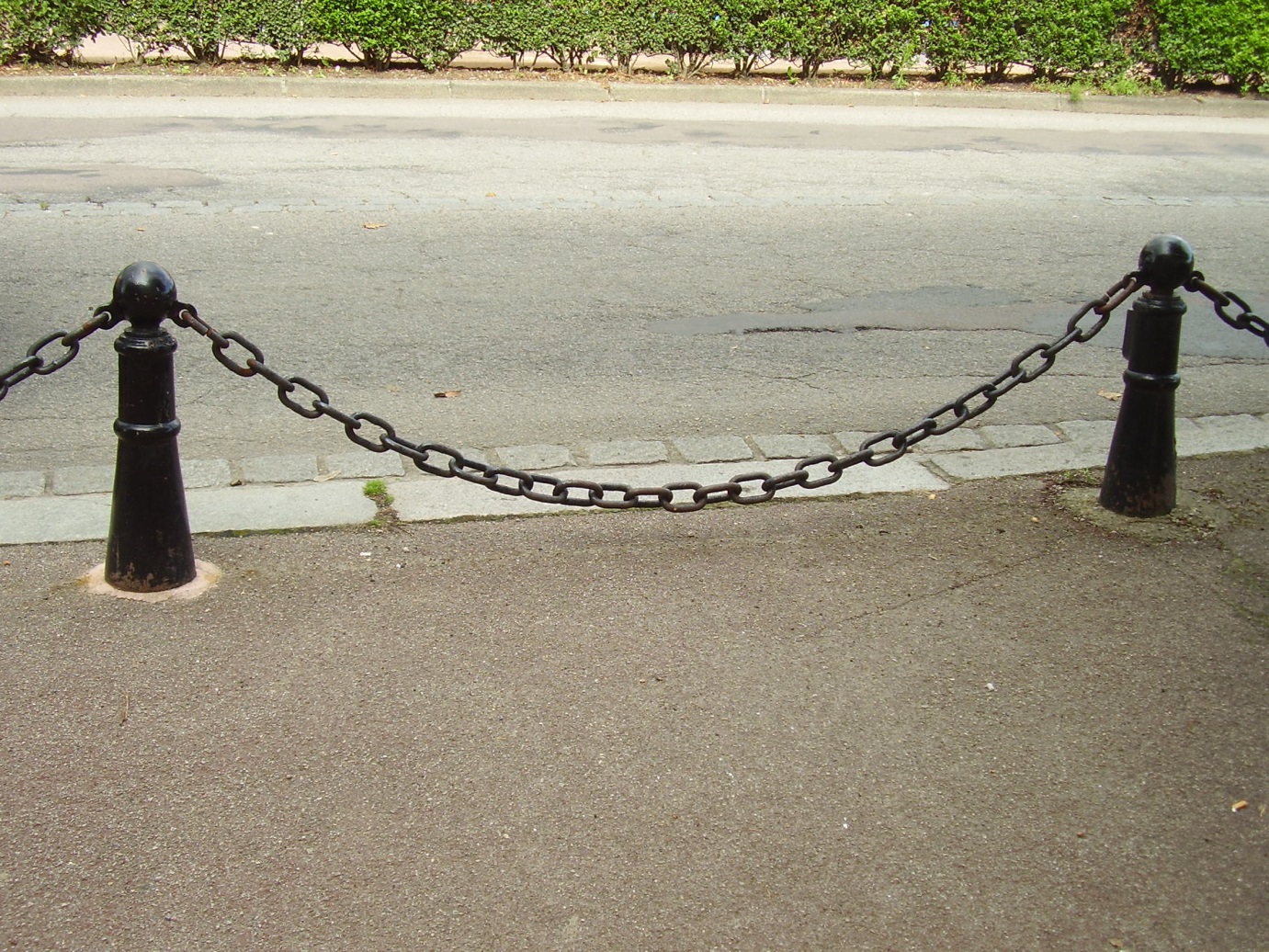
The flipped catenary arch so often used in stone-works would be ideal in this scenario, as the 3D printed material would have a very low tensile strength. When the material has been deposited in this shape, the primary forces on it are primarily compression, helping to ensure rigidity.
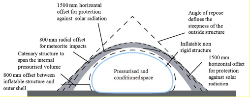
In order to protect against the three main types of radiation likely to be experienced by a lunar outpost (solar wind, solar glares, and galactic cosmic rays), regolith coverage of 1.5m thickness is required in the directions directly facing the sun. To protect against micrometeoroids (which may be travelling at speeds close to 18km/s upon impact), a thickness of 0.8m is required all over the structure. These two simultaneous thickness requirements can then be modelled together, with an ideal catenary arch of sufficient thickness then being laid over the two. Some additional modelling is also required to ensure that the resultant curve is structurally sound, and falls within the angle of repose of the regolith. This modelling can be seen in Figure 5, taken from the paper:
To create a protective shell such as the one seen above, a large amount of material would be required. This means that a large amount of binding agent would need to be transported to the moon, which is undesirable. To help reduce material transportation costs, a closed foam infill design has been chosen. This consists of fully enclosed bubbles (as are seen in foam), which can be filled with loose lunar regolith. The closed foam ensures that the loose regolith does not become removed, whilst the loose regolith affords sufficient thickness for the shielding requirements. The closed foam structure also has quite high compressive strength, allowing for it to better resist micrometeoroid strikes. The lack of connectivity between closed bubbles also means that if one bubble is pierced, the contents of other bubbles cannot also escape. It has been estimated that about 10% of the material within the external shell will contain binding material.
Once the closed foam infill method had been decided on, it became necessary to decide how large the foam bubbles should be, and with what internal wall thickness to use. Some estimates were made about the general structural performance of the dome were made (such as that if the dome is to “sag” slightly and spread horizontally, this would not be a bad thing). Based on these, it was decided that cell width should be in the order of 130-150mm. To simulate which infill patterns and cell density would provide the best strength, simulated 500mm cubes were created using the Finite Elements analysis software Scan&Solve. The relative density of the walls was adjusted so that each simulated cube had identical mass (i.e. the same amount of regolith/binding agent would be required). A 10KN load was applied to the top of each cube, and results were compared in terms of Von Mises stress (the load under which the cubes would begin to deform). It was found that the cube with higher wall thickness (and so a lesser number of larger cells) had the highest maximum value of Von Mises stress.
The next problem of the design process was simulating the lunar regolith itself. The chemical composition of the lunar soil is quite different to that on Earth, as is the distribution of grain sizes. It is important that an accurate representation of the lunar soil was used for trials, as the binding agent used may behave differently depending on chemical compositions of source material. The distribution of grain sizes will also have an impact on the vacuum reticulation (curing) timings. The binding agent chosen interacts with the metallic oxides naturally found in the regolith, enabling a crystallization process which envelops and binds the small grains of the regolith soil. While in lunar regolith these metallic oxides are available in their free form due to the lack of extensively available water. On Earth, these oxides are found in the more inert form of hydrated compounds. Because of this, lunar regolith simulants have to have added metallic oxides, and be tested in anhydrous conditions.
For proof of concept trials, it was decided that the off the shelf D-Shape 3D printer could be used. A 1:1 scale section of wall was to be printed, and so it was estimated that 2-3 metric tonnes of regolith simulant would be required. Commercially available regolith simulant are already available, such as the JSC-1A simulant from Orbitec Technologies, or the CAS-1 simulant from the Chinese Academy of Science. However, the quantity required for this test would cost around 40-50k Euros. Because of this, it was decided that an alternative should be sought. For the purpose of this project a new simulant was created, designated DNA-1. It was based on volcanic material found near Bolsena Lake in Italy. Crystallography through X-Ray diffraction was performed on DNA-1 to ensure that the major minerals within it were similar enough to those seen in lunar regolith; it was found that the composition was quite similar to JSC-1A, meaning that it was suitable for testing. Through milling, sieving, and remixing, the required granulometry was achieved.
As previously mentioned, the 3D printer used for the proof of concept design was the D-shape. This 3D printer has previously seen fame through 3D printing small houses using concrete. In a method very similar to Fused Deposition Modelling, substrate is premixed with a binding agent and extruded in layers to build up the final shape. In the case of the D-shape, these layers are around 6mm thick. The D-style consists of a large frame, with a spraying head moving along the axis to deposit the material. In the envisioned lunar outpost printing scenario, the spraying head would instead be mounted upon a small remotely operated vehicle which was capable of driving around the structure, depositing material much like a wasp does. A second vehicle could then push the loose regolith in to the cells during printing, or the primary robotic could perform this function simultaneously. For this test, a D-style printer was used to deposit binding agent on to layers of material selectively. After each layer of binding agent was completed, another layer of regolith was applied.
Testing of the methodology was performed in a vacuum chamber, to more accurately recreate the lunar environment. To avoid the binding agent from evaporating upon contact with the vacuum, a small tube was applied to the nozzle which allowed for the binding agent to be directly deposited in to the regolith layer. Due to size limitations, a D-style nozzle was used for these tests, but on a smaller model printer. Containers of binding agent were also stored within the vacuum for two days prior to printing as an early test of longevity in space. Results of testing were promising. Six balls were created via simple binding agent injections in to regolith, which were left to cure inside the vacuum. The resulting material was found to be comparable to a dolomite sand stone. Much like with plastic 3D printing, delamination can be a problem if printing is stopped and started. Temperature and weathering can also affect the final quality of the stone. It has been proposed that additional materials could also be mixed in to the structure to provide extra rigidity, if needed.
After the promising outcomes of these tests, some larger pieces were printed outside of the vacuum.
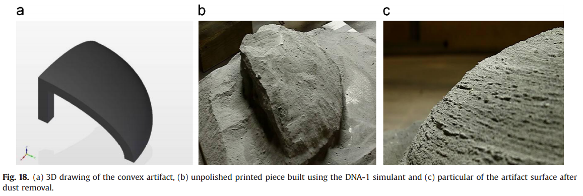
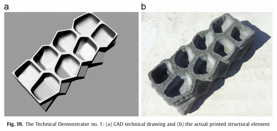
These test pieces proved to be quite successful. There were some slight discrepancies generated during the printing process, such as that the cell walls were much thicker than envisioned, causing the structure to be heavier than planned. It is expected that this may be less of an issue when printing in a vacuum, as vacuum-printed test pieces were found to be of much closer size to the amounts of binding agent used. It has been suggested that when printing in air, the capillary forces driving the binding agent between the grains of regolith are not being counterbalanced by the vacuum-induced evaporation.
One of the main issues with this whole methodology is that it would be required to transport large amounts of binding agent to the moon. As the binding agent is a fairly simple substance, it is proposed that the first structure to be built on the moon should contain a lab for the production of further binding agent. Various estimates have been carried out on carrying out such a first development project. The equipment required for the initial print would weigh in at roughly 8 tons. An average price of 200k Euros per kg of material to be transported to the moon was found, meaning that the cost of transporting such an amount of equipment to the moon would be roughly 1600 million Euros. Although this seems like a very high value, in the scheme of space technology it is quite reasonable. Perhaps in the future this cost will go down, and someone will finally try the idea out.
Be First to Comment